China
cn
中文
- What is strain?
- How is strain calculated?
- Why is the strain measured?
- How does force measurement with strain sensors work?
- Force measurement – when do I use a strain sensor and when a force sensor?
- How does the strain lead to the force?
- How does a strain sensor work?
- How does a strain gauge mechanoelectrical converter work?
- What is a Wheatstone bridge circuit?
- Are strain sensors fatigue endurable?
- What are the basic types of strain sensors?
What is strain?
How is strain calculated?
Why is the strain measured?
How does force measurement with strain sensors work?
Force measurement – when do I use a strain sensor and when a force sensor?
How does the strain lead to the force?
How does a strain sensor work?
How does a strain gauge mechanoelectrical converter work?
What is a Wheatstone bridge circuit?
Are strain sensors fatigue endurable?
What are the basic types of strain sensors?
What is strain?
Strain is the relative change in length of a component or structure under stress. This can consist of an extension (elongation) or contraction (compression). Strain can result from forces or moments (mechanical strain) applied to a structure, as well as thermal expansion in the case of temperature changes. The indirect force measurement via strain sensors determines the mechanical strain.
How is strain calculated?
The relative change in length is described as the strain ε in [m/m] and defined as the ratio of an absolute change in length Δ l to a total length l0. Strain does not have dimensions.
The unit symbol for strain is ɛ. As small strains occur when a component is monitored, the strain is given in [µm/m] (1 µm = 10-6 m). In European countries, strains are primarily given in [µm/m], whereas in Anglo-American countries, microstrain or microepsilon [µɛ] is more prevalent.
If a component is expanded, it is referred to as positive strain. If the component is compressed, the strain is negative.

Why is the strain measured?
In most cases, strain is measured to determine the degree of wear and thus the tension of a material through mechanical stress. At the same time, measurement of the strain can also provide information about the force causing the strain. This makes strain measurement a clever alternative for the determination of large forces. In laboratory settings, strain gauges are often glued to a component. However, in serial production it is easier to use screw-on strain sensors to create constant, high-quality conditions for indirect force measurement.
How does force measurement with strain sensors work?
For large force ranges and stiff constructions, strain sensors are a suitable alternative to force sensors. As opposed to force sensors, strain sensors are not installed directly in the force flow but are screwed onto the surface of the corresponding component. The stress on the machine structure leads to deformation. By measuring the surface strain, the strain sensors can be used to easily deduct the effective force. Indirect force measurement via strain sensors can cost-efficiently determine large forces using a small strain sensor.
In addition to the external screw-on strain sensors, there are also versions that determine strain via a drill hole. This can be useful depending on the system design.
Force measurement – when do I use a strain sensor and when a force sensor?

How does the strain lead to the force?
Each component subjected to a force (F) experiences a specific strain (ε). In the linear elastic area, this strain is always dependent on the E-module of the material (E), the cross-sectional area (A) of the material, and the force. Using these three parameters, the strain can be calculated as follows:

using the equation

With this equation, it is also easy to deduce the corresponding component stress. These calculations are based on Hooke's Law. In its simplest form, Hooke's Law determines the direct proportionality of the strain ε [m/m] and stress σ [N/mm2] of a specific material based on its elasticity module E [N/mm2].
The mechanical design and choice of material for the component are based on the mechanical stress that occurs. For steel materials with low strength, a lower stress and thus strain are permissible. For high-strength steel materials, a higher stress and strain are allowed.
The strain sensors have different measurement ranges that cover the expected strains.
E-module
In addition to the geometry and the force, the experienced strain of a component also always depends on the material of the component. The decisive parameter here is the E-module (elasticity module). It describes the proportional relationship between stress and strain during the deformation of a solid body in the linear-elastic area. The more rigid a material, the higher its E-module. The E-module for the tempering steel commonly used for strain sensors is E = 210,000 N/mm2.
The E-module of aluminum is around 70,000 N/mm2; the E-module of hard rubber is 5 N/mm2
The E-module of aluminum is around 70,000 N/mm2; the E-module of hard rubber is 5 N/mm2
Example calculation: from strain to force

Measured strain on the strain sensor: 240 µm/m
Steel rod width 20 mm x 20 mm -> Cross section A = 20 mm x 20 mm = 400 mm2
F= 400 mm2 x 210,000 N/mm2 x 240 x 10-6 m/m = 20,160 N
Steel rod width 20 mm x 20 mm -> Cross section A = 20 mm x 20 mm = 400 mm2
F= 400 mm2 x 210,000 N/mm2 x 240 x 10-6 m/m = 20,160 N
How does a strain sensor work?

With strain-gauge-based strain sensors, the mechanical parameter of force is converted into an electrical signal in four steps. The starting point is a component that is deformed by the application of force. This deformation is transferred via a frictional connection to the strain sensor. In turn, the strain sensor has a spring bellow made of tempering steel, on which strain is caused on the material surface by the external stress. The strain is measured using the strain gauges applied to the surface of the spring bellow. The strain gauges convert the mechanical strain into an electrical resistance change and act as mechanical-electrical converters. As a result of this change in resistance, they generate a voltage change proportional to the strain. With the help of the intelligent connection of the individual strain gauges to a Wheatstone bridge, even the smallest strains can measured.

How does a strain gauge mechanoelectrical converter work?
Strain gauges are at the core of Baumer force and strain sensors and are used to detect the strain on material surfaces. They usually consist of a supporting film (polyimide), a meander-shaped measuring mesh made of constantan, and a cover layer. The strain gauges convert the mechanical strain into an electrical resistance change and act as mechanical-electrical converters. The resistance change of the strain gauges takes place proportionally and is described as the k factor.
Designs
Metal strain gauges for sensor construction are available in various designs. In addition to the typical linear strain gauges, other typical designs include T rosette strain gauges, rosette strain gauges, and shear strain gauges:
Designs
Metal strain gauges for sensor construction are available in various designs. In addition to the typical linear strain gauges, other typical designs include T rosette strain gauges, rosette strain gauges, and shear strain gauges:

What is a Wheatstone bridge circuit?
The Wheatstone bridge circuit is a special circuit of electrical resistors that can help in precisely measuring electrical resistance changes. In the full-bridge circuit used in sensor construction, four strain gauges are always connected in a specific formation. The bridge circuit consists of two voltage dividers that are switched in parallel and are provided with the bridge power supply UB as a common source of power.

With the help of the Wheatstone bridge circuit, the smallest resistance changes can be precisely detected. Changes in the individual resistances lead to a bridge imbalance UA, which can be easily measured. The measuring signal of the bridge behaves ratiometrically and is proportional to the supply voltage. The typical measuring signal of strain gauge strain sensors ranges from 0.4 … 3.0 mV/V.
Are strain sensors fatigue endurable?
Mechanically, Baumer strain sensors are fatigue endurable for at least 10 million cycles at +/- for the entire strain range (e.g. +/- 500 µm/m). This way, processes with a high number of cycles and loads in the positive and negative direction can be monitored.
What are the basic types of strain sensors?
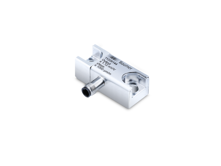
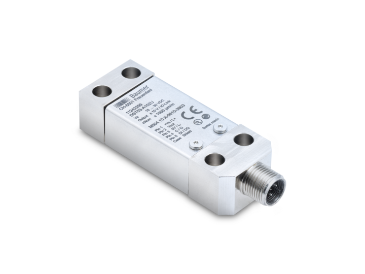
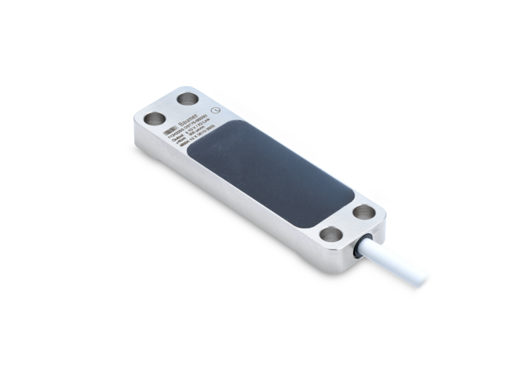
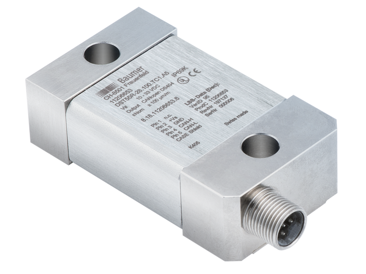
The Baumer product portfolio of strain sensors offers a nearly unlimited application potential. There are strain sensors for confined areas, standard industrial applications, as well as for rough outdoor applications.
回到顶部


